Determination of wood and byproducts elastic moduli using the Impulse Excitation Technique
The objective of this page is to introduce the theory and methodology for the non-destructive determination of the elastic moduli of wood and byproducts using the Impulse Excitation Technique. It is presented a literature review and the advances made in the application of this technique, already standardized for isotropic materials [1], for the characterization of wood and byproducts.
Introduction
Wood, both for its availability and characteristics, was one of the first materials used by man for structural means. It can be classified as a solid, organic compound, formed mainly by cellulose, whose main function is to maintain the support of trees [2]. It is a material that comes from stems that grow annually in diameter and length.
In addition to structural application, wood is also useful as a raw material for byproducts such as glued laminate, laminated plywood, particle boards and wood plastic composites (WPC).
![Figure 1 - Bridge over the Montmorency River, Montmorency Forest, Quebec, Canada. It has a span of 44 m, height of 33 m and width of 4.8 m [3].](/images/F1-EN-Wood-bridge-Montmorency-Canada-44m.jpg)
Figure 1 - Bridge over the Montmorency River, Montmorency Forest, Quebec, Canada. It has a span of 44 m, height of 33 m and width of 4.8 m [3].
Due to the microstructural characteristics of its natural origin, the physical properties of wood depend on the direction of loading [2]. The three main axis / directions of the woods are illustrated in Fig. 2 and listed below:
- Longitudinal (L): Axis parallel to the fibers (grain direction);
- Radial (R): Axis normal to the growth rings (perpendicular to the grain in the radial direction);
- Tangential (T): Axis perpendicular to the grain and tangent to the growth rings.
![Figure 2 - The three main axes / directions of wood with respect to the grain direction and the growth rings [4].](/images/F2-EN-Main-axes-directions-wood-grain-fiber-direction-growth-rings.png)
Figure 2 - The three main axes / directions of wood with respect to the grain direction and the growth rings [4].
Wood is classified as an orthotropic material because it presents orthogonal planes of symmetry in which the elastic properties are constant [5]. This classification is an approximation, because depending on the property under analysis it is possible to verify variations, for instance, along the growth rings.
The elastic moduli determination is crucial for the development, selection and quality control of wood and byproducts, as well to simulations and structural calculations. These applications are possible due to the sensitivity of the elastic moduli to the presence of discontinuities, defects, cracks, knots, microstructural changes and chemical composition [6]. One of the non-destructive techniques that has become popular for determining the modulus of elasticity is the Impulse Excitation Technique, the focus of this page.
Determination of the elastic moduli of wood with the IET
Technique fundamentals
The Impulse Excitation Technique determines the elastic moduli of a material based on the natural frequencies of vibration of a specimen with regular geometry (bar or cylinder). These frequencies are excited by a short mechanical impulse, followed by the acoustic response acquisition. A mathematical analysis is performed on the acoustic response in order to obtain the frequency spectrum. Then, the dynamic elastic moduli are calculated considering the geometry, mass, specimen dimensions and frequencies obtained by the acoustic response analysis [1].
For the excitation and detection of specific vibration modes, it is necessary to set up specific boundary conditions. Figure 3 presents a specimen support with a manual impulse device and an acoustic sensor positioned to excite and detect the flexural vibration mode.
![a) Basic set up to characterize the flexural vibration mode of a bar using the Impulse Excitation Technique [8]](/images/F3-A-EN-Setup-flexural-vibration-bar-Impulse-Excitation-Technique-Sonelastic.png)
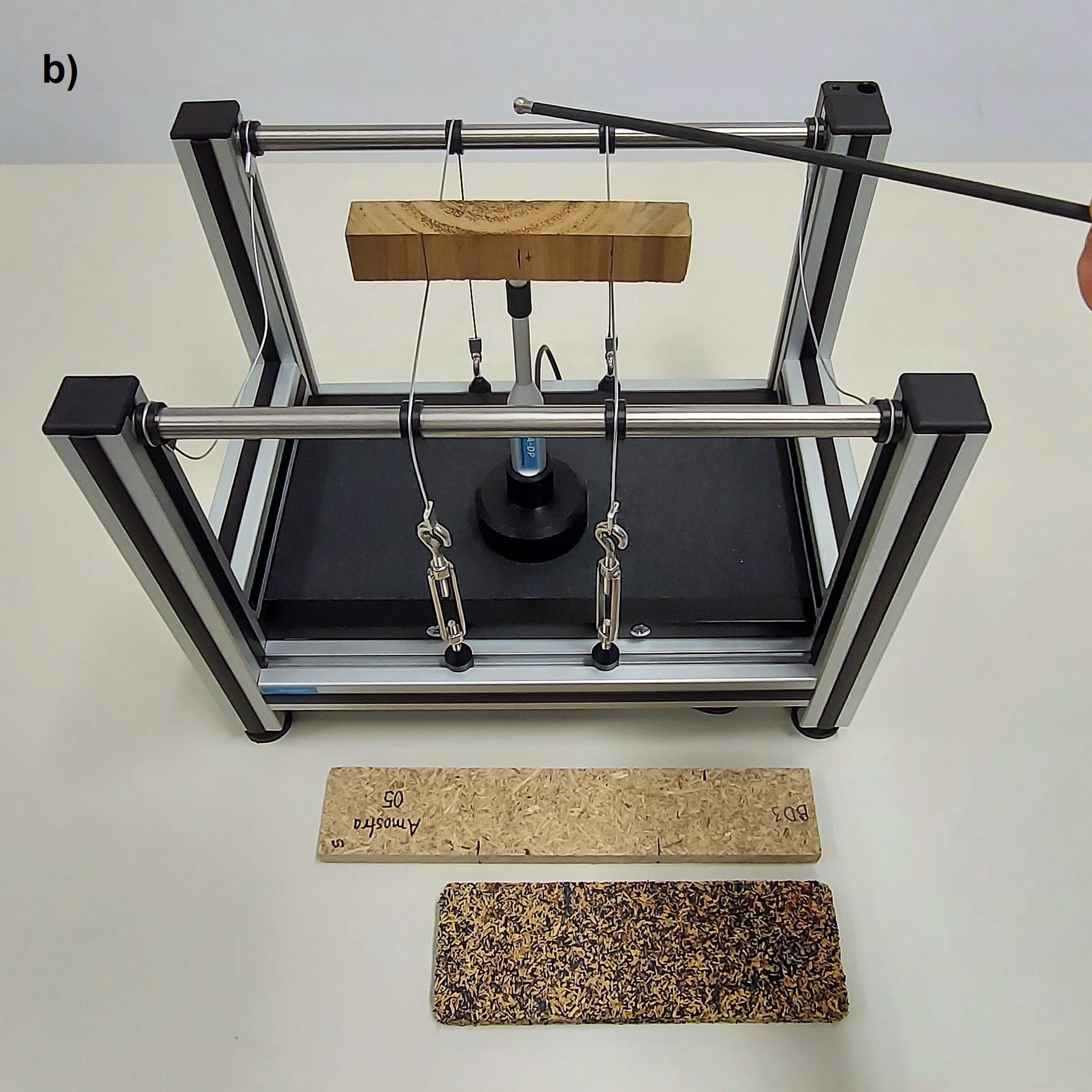
Figure 3 – a) Basic set up to characterize the flexural vibration mode of a bar using the Impulse Excitation Technique [8] and b) SA-BC support for bars and cylinders developed and manufactured by ATCP Physical Engineering.
The Young's modulus obtained by the Impulse Excitation Technique is named dynamic and always greater than or equal to that obtained by a quasi-static test. Nonetheless, it is possible to establish a correlation between them [7].
Vibration modes
A specimen may vibrate in different modes and for each mode there is a specific fundamental frequency. Figure 4 presents the main fundamental vibration modes [9].
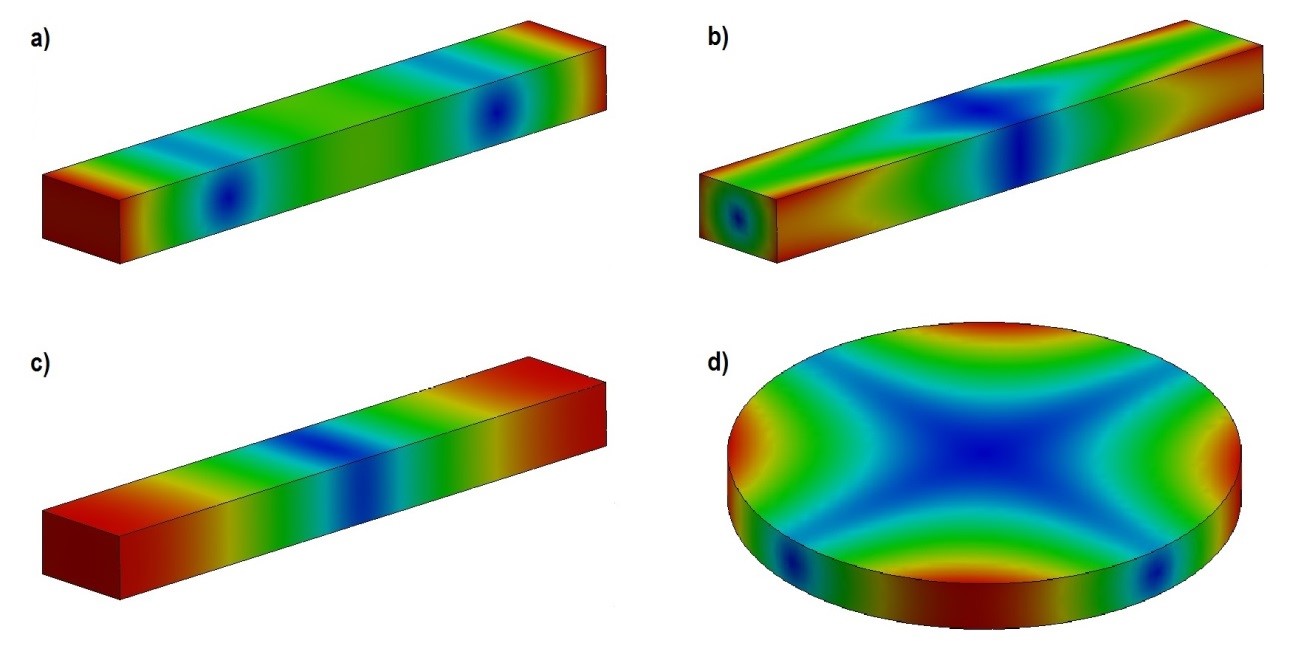
Figure 4 - Fundamental vibration modes: a) flexural, b) torsional, c) longitudinal, and e) planar. The blue region represents the area of minimum amplitude of vibration, whereas the red one represents the area of maximum amplitude.
The boundary conditions imposed on the specimen determine which mode of vibration will be excited. Figures 5 a-c [1,6] show the optimum boundary conditions for the main vibration modes of a bar, whereas Figure 5d shows the optimum boundary conditions for a disc. The corresponding dynamic elastic moduli are calculated based on the resonant frequencies from the excited vibration mode(s).
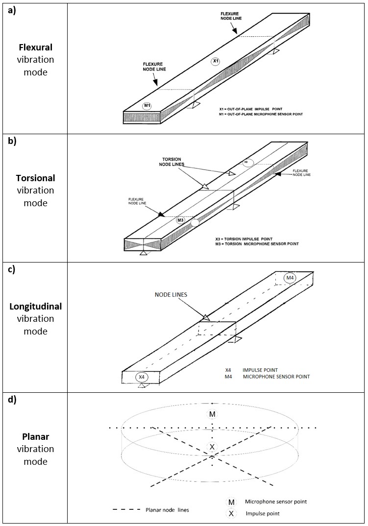
Figure 5 - Boundary conditions for the excitation of (a) flexural, (b) torsional, (c) longitudinal, and (d) planar fundamental vibration modes.
Elastic moduli of wood
The elastic properties of wood vary according to the orientation of fibers (grain direction) and growth rings. When they are determined using the Impulse Excitation Technique, it is important to take the orientation in consideration to report the results correctly. In the case of wood byproducts, the analysis is similar.
Table 1 - Elastic moduli determined by the Impulse Excitation Technique as a function of the fibers’ orientation and vibration modes.
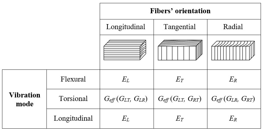
Table 1 presents the elastic moduli of wood that can be determined using the Impulse Excitation Technique in dependence of the orientation of the fibers / grains and of the vibration mode. The terms used in Table 1 are defined as [5,10]:
EL – Longitudinal Young’s modulus;
ET – Tangential Young’s modulus;
ER – Radial Young’s modulus;
Geff – Effective shear modulus determined by the Sonelastic® system, it corresponds to a combination of the Gij moduli shown in parentheses [5];
GLT – Modulus of Rigidity associated to shear strain at the LT plane resulting from shear stresses in the LR and RT planes;
GRT – Modulus of Rigidity associated to shear strain at the RT plane resulting from shear stresses in the LR and LT planes;
GLR – Modulus of Rigidity associated to shear strain at the LR plane resulting from shear stresses in the RT and LT planes.
• Young’s modulus
-By longitudinal vibration mode
When the specimen is excited in longitudinal mode (verify boundary conditions in Figure 5c), the elastic modulus obtained will refer to the orientation or axis parallel to the specimen’s length. Therefore, the orientation of the specimen will determine the elastic modulus being measured, as presented in Table 1 (EL, ER, ET or a combination of these directions).
- By flexural vibration mode
When a specimen is bended, there are both tension and compression present as shown in Fig. 6. For homogeneous and isotropic materials, the elastic modulus obtained from a bending test coincides with the elastic modulus obtained in an axial test (longitudinal direction). Similarly, the dynamic elastic modulus determined by the flexural vibration mode is the same as by the longitudinal vibration mode [11]. However, in bending, the surface of the specimen is subjected to stresses greater than its center. For this reason, if a specimen presents the stiffness of the surface different from the inside (for example, if there is a stiffness gradient along the thickness), or if the specimen presents small flaws such as pores, cracks and micro-cracks on the surface, there will be a difference between the values determined by flexural and longitudinal vibration modes [10, 12-14].
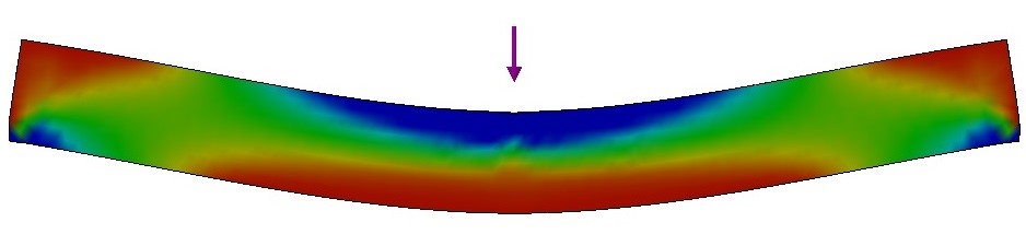
Figure 6 - Regions under tension (red) and under compression (blue) during a bending test.
• Shear modulus
-By torsional vibration mode
When a specimen is submitted to a torsion test, two values of shear moduli act concomitantly on the material. If there is torsion such as described in Figure 5b, the acting shear modulus are associated with the surfaces being sheared (the four laterals of the specimen). Therefore, the shear modulus calculated using fundamental torsional frequency will correspond to an effective modulus. This way, the result obtained by the Sonelastic® will be a combination of the active shear moduli (Table 1 indicates the active shear moduli that comprise the effective value for each orientation) [5].
•Poisson’s ratio
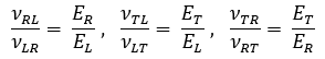
The Impulse Excitation Technique is not suitable to characterize the Poisson’s ratio of orthotropic materials such as wood. However, based on the Elasticity Theory and using the stiffness matrix, it is possible to obtain correlations between the Poisson’s ratio and the elastic moduli. Next, find these relations (stiffness matrix is described in Appendix A):
To calculate the elastic moduli, it is necessary to estimate the Poisson's ratio. Table 2 presents an estimation and uncertainty according to the average values presented by typical wood. It is worth mentioning that the sensitivity of Young's modulus to the error in Poisson's ratio estimation is low.
Table 2 - Estimated Poisson coefficient and respective uncertainty for the calculation of the elastic modulus of wood in dependence of fiber orientation [5].
![Table 2 - Estimated Poisson coefficient and respective uncertainty for the calculation of the elastic modulus of wood in dependence of fiber orientation [5].](/images/T2-EN-Estimated-Poisson-LT-LR-RT-RL-TR-TL-Longitudinal-Radial-Tangencial-Wood.jpg)
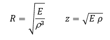
• Derived parameters
From the elastic modulus and density, it is possible to calculate the wood sound radiation coefficient (R) and acoustic impedance (z) [19]. The modulus of elasticity to be used must be chosen according to the vibration mode.
Expected values for softwood
Wood can be classified as low, medium or high density. Most high-density wood have higher values of elastic modulus and strength [2]. Table 3 presents predicted elastic moduli values as a function of EL for softwood, showing the elastic properties of this type of wood according to the EL variation [5].
Table 3 - Predicted elastic parameters as function of EL for softwood (values in GPa) [5].
![Tabela 3 - Módulos elásticos em função de EL para madeiras de baixa densidade (valores em GPa) [5].](/images/T3-EN-Predicted-elastic-parameters-EL-softwood-Er-El-Et-Glr-Glt-Grt.jpg)
The Young's modulus obtained by the Impulse Excitation Technique is dynamic and always greater than or equal to that obtained by a quasi-static test. However, it is possible to establish a correlation between the static and the dynamic moduli. Below is an example of correlation, in MPa, between the Young's modulus determined in the longitudinal direction by quasi-static test (ELE) and the dynamic Young's modulus determined in the longitudinal direction by Impulse Excitation Technique (ELD) [7]:
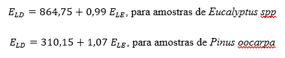
Example – Eucalyptus wood
This example describes the determination of the modulus of elasticity of a Eucalyptus wood (Eucalyptus spp) in two orientations using the Impulse Excitation Technique and the Sonelastic® Systems.
Materials and methods
Figure 7 shows a top view of a tree section, the concentric circles correspond to its growth rings. In this figure, three possible specimen cuts are illustrated. The specimens indicated by (1) and (2) present ideal cuts to obtain ET and ER, respectively. In (1), the length direction is tangent to the growth rings and in (2), the length direction is parallel to the direction of the growth rings [5].
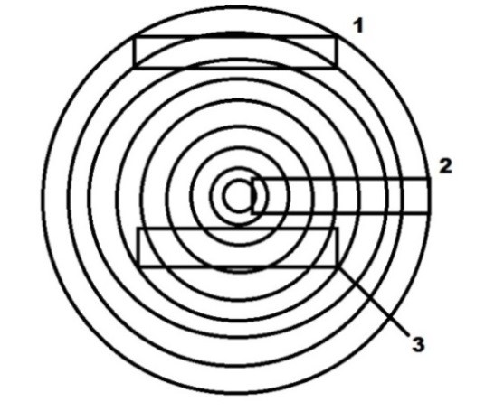
Figure 7 - Identification of the best places to cut the wood specimens to determine ET (1) and ER (2). The cut presented in (3) combines both R and T directions.
If the specimen combines the R and T directions as indicated in (3), the values obtained will be effective and result from a combination between ER and ET.
Figures 8 and 9 indicate the fibers orientation of the tested wood specimens. The specimen in Figure 8 presents its fibers aligned parallel to its length (these bars were indicated by “L” index). The specimen in Figure 9 has its fibers transversely oriented and there is a combination between the radial and tangential direction along its length (these bars were indicated by “RT” index).
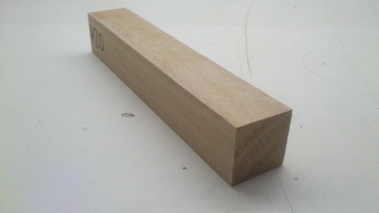
Figure 8 - Specimen with fibers in the length direction (L).
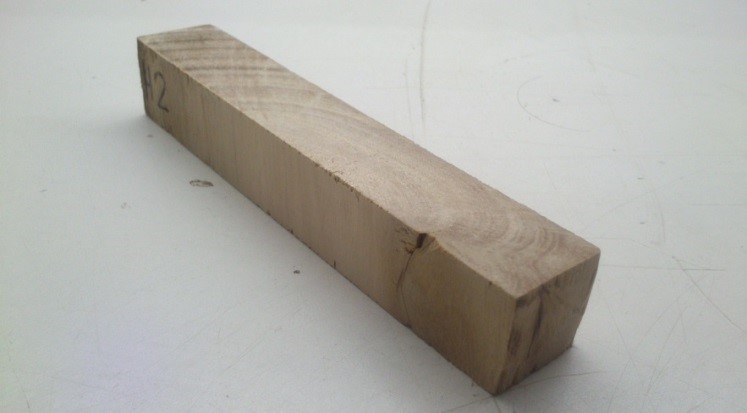
Figure 9 - Specimen with fibers in the radial and tangential directions (RT).
The specimens were tested with regards the main vibration modes (flexural, torsional and longitudinal) using the SA-BC adjustable support for bars and cylinders, the IED Automatic Electromagnetic Impulse Device, the CA-DP directional acoustic sensor, and the Sonelastic Software® (these items are part of the Sonelastic® System for medium-sized specimens shown in Fig. 10).
A Poisson’s ratio of 0.25 ±0.25 was adopted to calculate the elastic moduli. As mentioned earlier, this value may vary significantly according to the orientation of the fibers. For this reason, an uncertainty of 0.25 was considered to include all the possible values for this property. Note: the influence of the Poisson’s ratio when calculating the elastic moduli is low, this can be verified by checking the uncertainties presented in Tables 4 and 5.
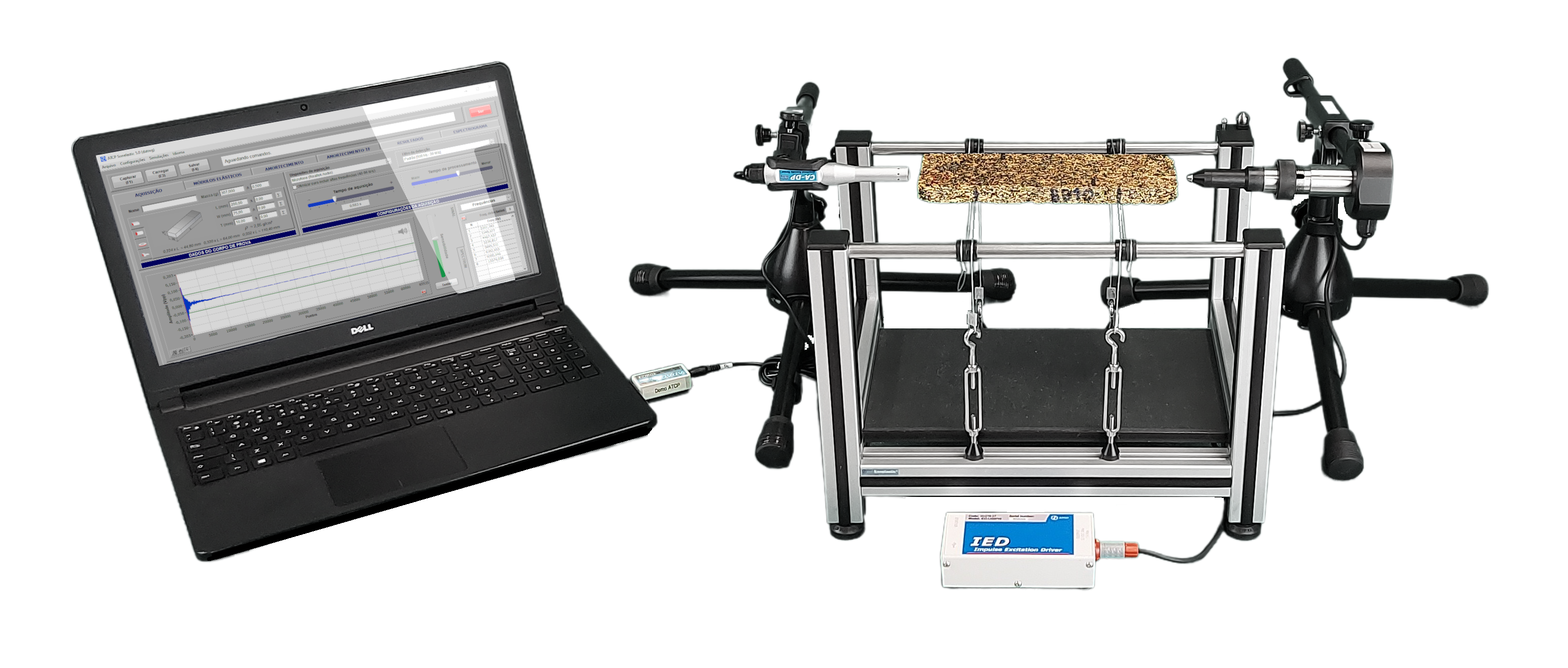
Figure 10 - Sonelastic® equipment developed by ATCP Physical Engineering for elastic moduli determination by Impulse Excitation Technique.
Results and discussions
The specimens were organized into two groups according to the fiber direction. Tables 4 and 5 show the elastic moduli determined at each vibration mode.
Table 4 - Elastic moduli obtained as a function of the vibration mode (“RT” specimens).
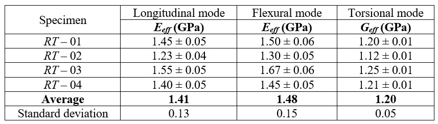
Table 5 - Elastic moduli obtained as a function of the vibration mode (“L” specimens).
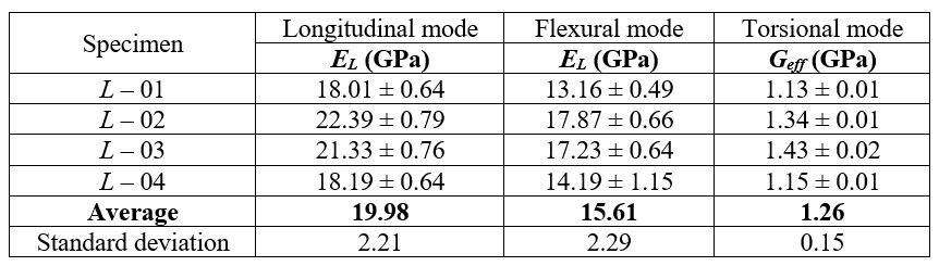
The Young’s modulus in Table 4 are effective because the specimens present a combination between R and T directions aligned parallel to their lengths. The values measured for “L” specimens are represented by EL because the fibers are parallel to the length (Table 5).
There is a difference between elastic moduli values obtained in longitudinal and flexural directions, mainly for the “L” specimens. This difference is due to the presence of surface defects, which influence more the results in the flexural vibration mode; there may also be a gradient of stiffness along the thickness, so that the surface is more or less rigid than its interior, influencing the results. For wood, there is a tendency for the properties obtained with the longitudinal vibration mode to be superior to those obtained in the flexural mode. [10,12-14].
Finally, Geff consists of an effective shear modulus, which is a combination of the moduli related to the planes being sheared on the torsional vibration. For example, the Geff value for the “L” specimens is a combination between GLR and GLT. For “RT” specimens, this analysis is even more complex because the direction of the specimen’s length does not correspond to a defined orientation (L, R or T).
Final considerations
Wood and byproducts are anisotropic materials and its elastic moduli depend on the fibers / grains orientation and vibration mode when tested by Impulse Excitation Technique.
From the orientation of the specimen and the boundary conditions for the flexural and longitudinal vibration modes, it is possible to obtain the main elastic moduli of wood: EL, ER and ET. The Impulse Excitation Technique also allows the characterization of effective shear moduli by torsional vibration mode.
Examples of customers and applications in the area of composites, wood and by-products.
References
[1] ASTM International. Standard Test Method for Dynamic Young’s Modulus, Shear Modulus, and Poisson’s Ratio by Impulse Excitation of Vibration; ASTM E 1876. 2007. 15 p.
[2] DİNÇKAL, Ç. Analysis of Elastic Anisotropy of Wood Material for Engineering Applications. Journal of Innovative Research in Engineering and Science, Global Research Publishing, pp. 67-80, abr. 2011.
[3] Ponte de Madeira na floresta de Montmorency. Disponível em:
[4] Adaptado de CALIL JUNIOR, C.; LAHR, F.A.R.; DIAS, A.A. Dimensionamento de elementos estruturais de madeira. Barueri: Manole, 2003. 152 p.
[5] BODIG, J., JAYNE, B. A. Mechanics of wood and wood composites. Malabar (EUA), Krieger Publishing Company, 1993.
[6] COSSOLINO, L.C., PEREIRA, A.H.A. Módulos elásticos: visão geral e métodos de caracterização. Informativo Técnico – ATCP Engenharia Física. Out/2010. Disponível em:
[7] SEGUNDINHO, P.G.A., COSSOLINO, L.C., PEREIRA, A.H.A, JUNIOR, C.C. Aplicação do método de ensaio das frequências naturais de vibração para obtenção do módulo de elasticidade de peças estruturais de madeira. Revista Árvore, Viçosa-MG, v.36, n.6, p.1155-1161, 2012.
[8] Esquema de posicionamento e caracterização de acordo com a norma ASTM E1876. Disponível em:
[9] HEYLIGER, P., UGANDER, P., LEDBETTER, H. Anisotropic Elastic Constants: Measurement by Impact Resonance. Journal of Materials in Civil Engineering, pp. 356-363, set/out 2001.
[10] WANGAARD, F.F. The Mechanical Properties of Wood. New York: John Wiley & Sons, Inc, 1950.
[11] KAW, A.K. Mechanics of composite materials. Boca Raton: Taylor & Francis Group, 2 ed, 2006, 457 p.
[12] ROCHA, J.S., PAULA, E.V.C.M. de, SIQUEIRA, M.L. Flexão Estática em amostras pequenas livres de defeitos. Acta Amazonica, Manaus, p. 147-162. 1988.
[13] CHO, C.L., Comparison of Three Methods for Determining Young’s Modulus of Wood. Taiwan Journal for Science, pp. 297-306, Maio/2007.
[14] BUCUR, V., Acoustics of Wood. 2ª ed. Germany: Springer, 2006. p. 393.
[15] WANGAARD, F. F. The Mechanical Properties of Wood. John Wiley & Sons, Inc., New York, 1950.
[16] CALLISTER Jr., W.D. Materials Science and Engineering. 7ª ed. New York: John Wiley & Sons, Inc, 2007.
[17] Curva Tensão-Deformação. Disponível em:
< http://www.ctb.com.pt/?page_id=1471>. Acessado em: 08 de Julho de 2014.
[18] NYE, J.F. Physical Properties of Crystals: their representation by tensors and matrices. Oxford: At the Clarendon Press. 1957.
[19] Ulrike G.K. Wegst, Wood for sound. American Journal of Botany 93(10):1439-1448. October 2006.