Determination of composite materials elastic moduli using the Impulse Excitation Technique
The purpose of this section is to present the theory and methodology for composites non-destructive elastic moduli determination. The following content comprises a literature review and the advances made by ATCP Engenharia Física in the application of Impulse Excitation Technique [1] for composite materials characterization.
Introduction
The definition of composite materials varies according to author, depending on the aspects and considerations taken into account. According to Chawla [2], to be classified as a composite, a material should comply with some conditions. First, it must be manufactured, meaning that it must be projected and produced by man; in addition, it must consist of an adequate combination of distinct physical and/or chemical phases; lastly, its characteristics are not achieved by any of the isolated components.
Intrinsic composite materials comprise at least two components: the matrix, which can be ceramic, metallic or polymeric; and the reinforcement, which may be in fibers or particles form. Structural composites, on the other hand, may be laminates or sandwich panels (Fig. 1).
![Figure 1 - Classification of composite materials [3].](/images/F1-EN-Classification-composite-materials.jpg)
Figure 1 - Classification of composite materials [3].
The advent of high-tech composites began in the 1960s by the demand for materials with high resistance and low density. The main areas of application included the civil construction sector, aerospace and power industry [2,4]. Currently, composites are used in several industries, being employed to manufacture a wide range of products from simple artifacts to cars [5] and high-performance vessels (Fig. 2).
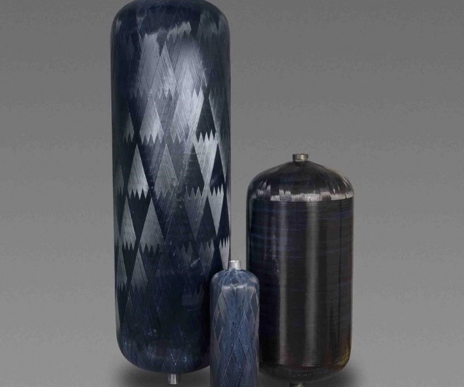
Figure 2 - Pressure vessels for natural gas manufactured by 3M with composite materials.
Determining the elastic moduli of composites is crucial for development, material selection and quality control, as well as for enabling reliable finite element analyses and structural calculations. One of the non-destructive techniques used to evaluate the elastic moduli and has been growing within this sector is the Impulse Excitation Technique, which is the focus of this section. Figure 3 shows CFRP and UHMWPE specimens prepared for elastic modulus determination by the Impulse Excitation Technique.
![Figure 3 - Specimens of an ultra-high molecular weight polyethylene (UHMWPE) for ballistic armor and of an aeronautical monolithic panel made of carbon fiber reinforced plastic (CFRP). They are prepared for elastic moduli non-destructive characterization by Impulse Excitation Technique with Sonelastic® Systems [6].](/images/F3-EN-Specimens-UHMWPE-ballistic-armor-CFPR-carbon-fiber.png)
Figure 3 - Specimens of an ultra-high molecular weight polyethylene (UHMWPE) for ballistic armor and of an aeronautical monolithic panel made of carbon fiber reinforced plastic (CFRP). They are prepared for elastic moduli non-destructive characterization by Impulse Excitation Technique with Sonelastic® Systems [6].
Composites elastic moduli determination applying IET
Technique foundations
The Impulse Excitation Technique [1] consists in determining the elastic moduli of a material based on the natural frequencies of vibration of one or more specimens in regular geometry (bar, cylinder, disc or ring). These frequencies are excited by a short duration mechanical impulse, followed by acoustic response acquisition with an acoustic sensor. After that, a mathematical processing is performed in order to obtain the frequency spectrum. Based on this, the dynamic elastic moduli are calculated considering the geometry, mass, specimen dimensions and frequencies obtained from the acoustic response processing [1].
For the required vibration mode excitation, it is necessary to impose specific boundary conditions. Figure 4 shows a specimen support with manual impulse device and acoustic sensor positioned to measure the Young’s modulus of a rectangular bar in flexural vibration mode.
![Basic set up for the characterization of a bar in flexural vibration mode using the Impulse Excitation Technique [7].](/images/F4-A-EN-Setup-bar-flexural-vibration-mode-Impulse-Excitation-Technique-elastic.png)
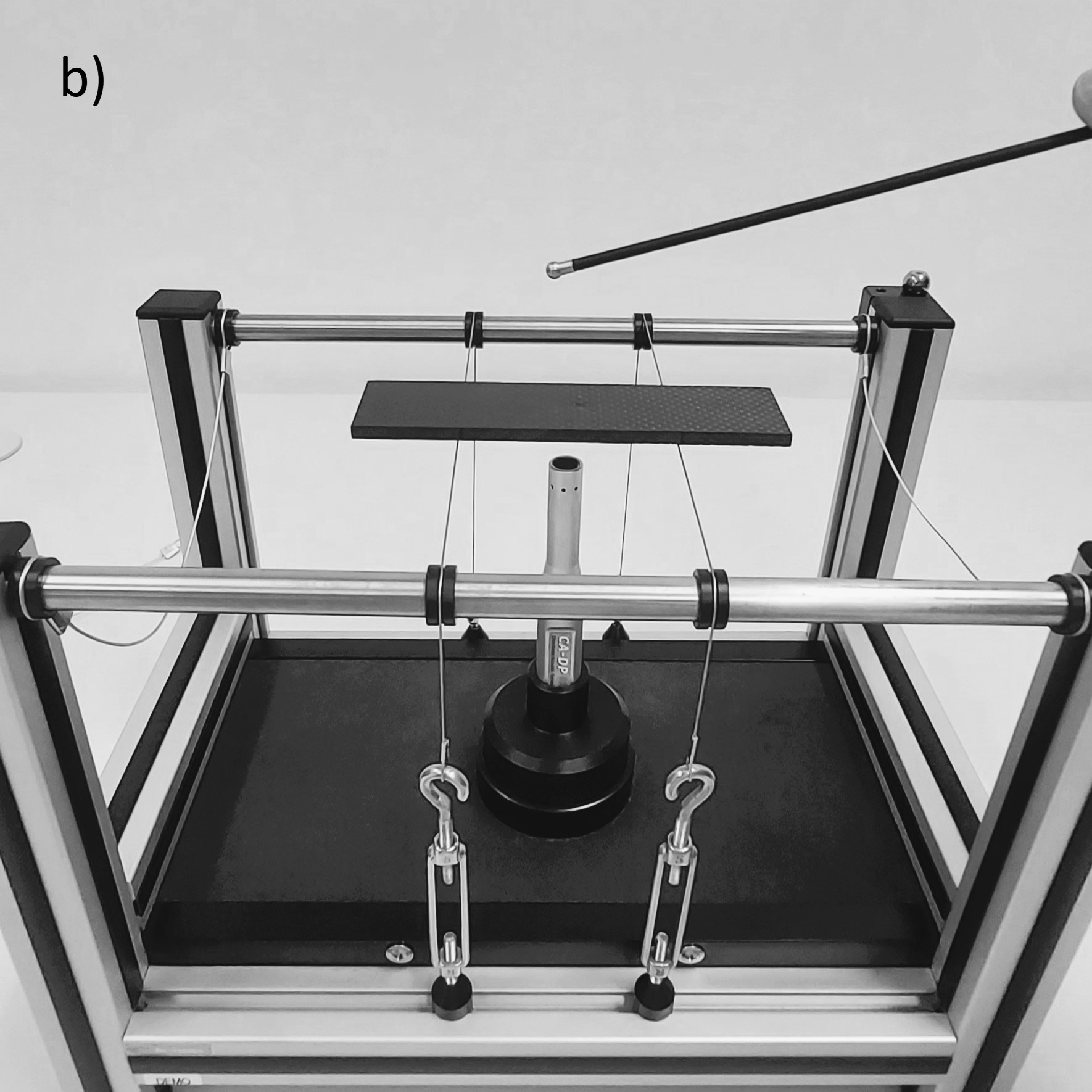
Figure 4 - a) Basic set up for the characterization of a bar in flexural vibration mode using the Impulse Excitation Technique [7] and b) SA-BC adjustable support for bars and cylinders with a specimen of aeronautical composite.
Vibration modes
A specimen may vibrate in different modes and for each mode there is a specific fundamental frequency. Figure 5 shown the main fundamental vibration modes [8].

Figure 5 - Fundamental vibration modes: a) Flexural, b) Torsional, c) Longitudinal and d) Planar. Blue areas represent the regions of minimum amplitude of vibration, whilst the red areas represent the regions of maximum amplitude of vibration.
The natural frequencies for these modes depend on the geometry, mass, dimensions and elastic moduli of the specimen. The boundary conditions determine the mode of vibration. Figure 6 a-c shows the optimum boundary conditions for the main vibration modes of a rectangular bar, whilst Figure 6d shows the same for a disc [1]. Based on the specimen resonance frequencies and by employing the ASTM E1876 [1] equations, it is calculated the corresponding dynamic elastic moduli.
![Figure 6 – Support, excitation and sensing for (a) Flexural, (b) Torsional, (c) Longitudinal and (d) Planar vibration modes [1].](/images/F6-EN-Support-excitation-sensing-Flexural-Torsional-Longitudinal-Planar-modes-vibration.jpg)
Figure 6 – Support, excitation and sensing for (a) Flexural, (b) Torsional, (c) Longitudinal and (d) Planar vibration modes [1].
Elastic moduli of composites
Most composite materials show some degree of anisotropy, that is, their properties depend on the stress direction. Consequently, when measured using the Impulse Excitation Technique, it is important to know and report the material symmetry and the specimen orientation.
Appendix A of our Technical-scientific Informative ITC-06 describes the elasticity theory applied to composite materials based on general micro and macromechanical approaches for the three main symmetries. Figure 7 shows a non-isotropic generic structure, such that, for the characterization of the main elastic modulus (E1, E2, E3) it is necessary three specimens in directions 1, 2 and 3).
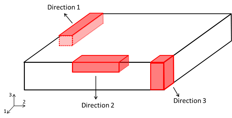
Figure 7 - Diagram of a generic structure, detailing how to obtain specimens in the three main directions.
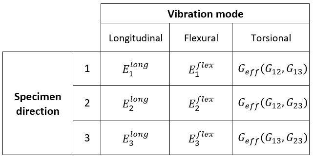
Table 1 indicates the elastic moduli that can be determined using the Impulse Excitation Technique and the guidelines for an orthotropic specimen (Figure 7). In this table, the terms used [9] are defined as:
E1 – Young’s modulus in direction 1;
E2 – Young’s modulus in direction 2;
E3 – Young’s modulus in direction 3;
Geff – Combination of Gij moduli shown in parentheses [14];
G13 – Shear modulus associated with strains on plan 13;
G23 – Shear modulus associated with strains on plan 23;
G12 – Shear modulus associated with strains on plan 12.
Table 1 - Elastic moduli determinable by Impulse Excitation Technique according to the specimen orientation and vibration modes.
• Young's modulus
-By longitudinal vibration mode
When the specimen is loaded in longitudinal mode (see boundary conditions in Figure 6c), the elastic modulus measured will be in the direction of the length of the specimen. That is, the orientation of the sample will determine which modulus is being determined (E1, E2, E3 or a combination), as shown in Table 1.
-By flexural vibration mode
When a material is bended, there are simultaneous tension and compression stresses, as illustrated in Figure 8 [10]. For homogeneous and isotropic materials, the elastic modulus obtained in a bending test coincides with the elastic modulus measured in the longitudinal direction. Therefore, the dynamic elastic modulus obtained through the flexural vibration mode is the same as that obtained through the longitudinal vibration mode [10]. However, it is known that, in bending, the surface of the material is the region where the highest values of normal stress are present. For this reason, if the specimen stiffness is different at the surface compared to the center (for example, if there is a stiffness gradient along the thickness) or if the sample has small surface defects such as pores, cracks and microcracks, there will be a discrepancy in the values obtained by flexural and longitudinal mode. There are several works focused on the evaluation of woods that report differences in values according to the vibration mode [8,11-13].
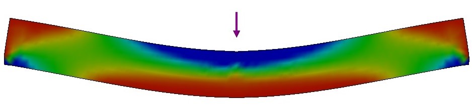
Figure 8 - Regions of tension (red) and compression (blue) stress during a bending test.
• Shear modulus
-Torsional vibration mode
When a material is subjected to a torsion test, two values of shear modulus act concomitantly on transversely isotropic and orthotropic materials. If there is a torsion such as described in Figure 5b, the shear modulus obtained will be associated with the surfaces that are being sheared (the four lateral surfaces of the specimen). Therefore, the shear modulus calculated using fundamental torsional vibration frequency correspond to an effective modulus. Thus, the results obtained by Sonelastic will be a combination of the active shear moduli (Table 1 indicates the active shear moduli that comprise the effective value for each orientation) [14].
• Poisson’s ratio
Poisson’s ratio determination applying Impulse Excitation Technique is indirect. It is performed by the Young’s modulus and the shear modulus correlation or by the reciprocal Poisson’s ratio equation. The equations are from the Elasticity Theory and directly related to the stiffness matrices and material symmetry are shown below:
-Isotropic material:

-Transversely isotropic material:
-Orthotropic material:
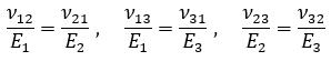
Where: E is the Young’s modulus, G the shear modulus and v the Poisson’s ratio of an isotropic material. Appendix B of Technical-scientific Informative ITC-06 describes these equations deduction as well as more detailed explanations on measuring Poisson's ratio using the Impulse Excitation Technique.
Material symmetry and the elastic moduli obtained by Sonelastic®
As previously mentioned, composite materials may present different types of symmetry regarding their mechanical properties. Thus, it is necessary to know the symmetry, the aimed elastic moduli and the orientations. Table 2 shows a summary of the information presented up to this point, including details of the elastic moduli measurable by Sonelastic®.
Table 2 – Elastic moduli according to symmetry, required specimens and elastic moduli possible to be determined with the Impulse Excitation Technique (IET).
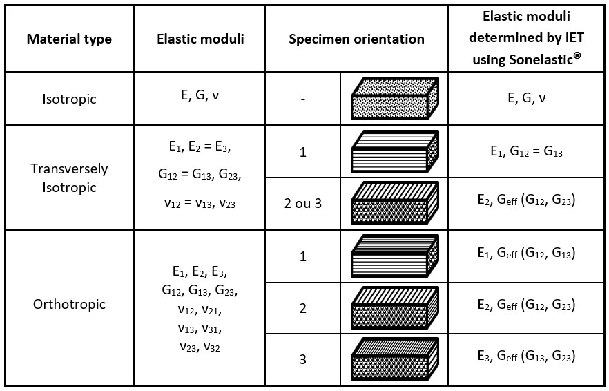
To determine the elastic moduli of composite materials using the Impulse Excitation Technique it is necessary to prepare specimens with specific orientations according to the material symmetry. It worth mentioning that it is also possible to measure specimens containing fibers in intermediate angles (between 0º and 90º), so that the properties measured in these directions are in agreement with the specimen orientation.
Final Considerations
The elastic moduli of composites, materials formed by the combination of two or more materials of different nature, may be non-destructively measured by Impulse Excitation Technique using Sonelastic® Systems. For that, it is necessary to know the composite symmetry in order to prepare specimens according to the material's directions.
Examples of customers and applications related to composites.
References
[1] ASTM International. Standard Test Method for Dynamic Young’s Modulus, Shear Modulus, and Poisson’s Ratio by Impulse Excitation of Vibration. ASTM E1876-21. 2021.
[2] CHAWLA, K. K., Composite Materials: Science and Engineering. 3 ed. New York, Springer, 2012.
[3] Translated from: composite classification. Available at:
[4] DANIEL, I. M., ISHAI, O. Engineering Mechanics of Composite Materials. New York, Oxford University Press, 1994, 395 p.
[5] Pressure vessel for natural gas manufactured by 3M. Available at:
[6] Available at: < https://www.sonelastic.com/en/applications/composites-woods.html>. Accessed on August 08, 2022.
[7] Positioning and characterization scheme in accordance to ASTM E1876. Available at:
[8] HEYLIGER, P., UGANDER, P., LEDBETTER, H. Anisotropic Elastic Constants: Measurement by Impact Resonance. Journal of Materials in Civil Engineering, pp. 356-363, set/out 2001.
[9] Adapted from WANGAARD, F.F. The Mechanical Properties of Wood. New York: John Wiley & Sons, Inc, 1950.
[10] KAW, A.K. Mechanics of composite materials. 2 ed. Boca Raton, Taylor & Francis Group, 2006, 457 p.
[11] ROCHA, J.S., PAULA, E.V.C.M. de, SIQUEIRA, M.L. Flexão Estática em amostras pequenas livres de defeitos. Acta Amazonica, Manaus, p. 147-162. 1988.
[12] CHO, C.L., Comparison of Three Methods for Determining Young’s Modulus of Wood. Taiwan Journal for Science, pp. 297-306, Maio/2007.
[13] BUCUR, V., Acoustics of Wood. 2ª ed. Germany, Springer, 2006. p. 393.
[14] BODIG, J., JAYNE, B. A. Mechanics of wood and wood composites. Malabar (EUA), Krieger Publishing Company, 1993.
[15] GIBSON, R. F. Principles of composite material mechanics. USA, 1994, 425 p.
[16] CALLISTER Jr., W.D. Materials Science and Engineering. 7ª ed. New York: John Wiley & Sons, Inc, 2007.
[17] Translated from stress-strain graph. Available at:
< http://www.ctb.com.pt/?page_id=1471>. Accessed on July 8, 2014.
[18] NYE, J.F. Physical Properties of Crystals: their representation by tensors and matrices. Oxford: At the Clarendon Press. 1957.
[19] TSAI, S. W. Theory of Composites Design. Stanford: Stanford University, 2008, 230 p.